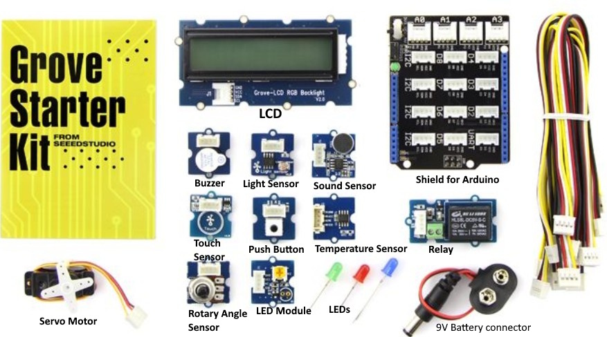
As part of a Girls‘ Day program, my daughter and I are preparing a workshop using the Grove-Starter Kit for Arduino. The Grove Kit comes with several sensors that are easy to connect and a shield to connect these modules directly to an Arduino UNO:
When we work with a micro-controller like Arduino, we program a task to be performed by the device attached to the output. Usually this task also depends on the value/state of the input. The inputs and the outputs can have a digital value (0 or 1) or be analog (a wide range of values, not only 1 or 0).


With the 9V battery connector, you can power the Arduino and operate your circuit as a stand-alone module.
For this workshop, we are going to program the Arduino using Codecraft for the first examples. Follow the link to install it and get an introduction, if you haven’t used it yet. You can create your program directly on the web or download Codecraft to your laptop or PC. If you want to upload your program (from the web-version) to your Arduino board, you will have to download the Codecraft Assistant as well.
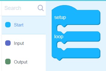
The main procedure block is inside the Start tab on the left, you can use your mouse to drag it to the working area. The main procedure includes two sub-procedures: setup and loop. The code in setup will run once when the Arduino is powered, the instructions in loop will run repeatedly.
LED blinking – LED as a digital output
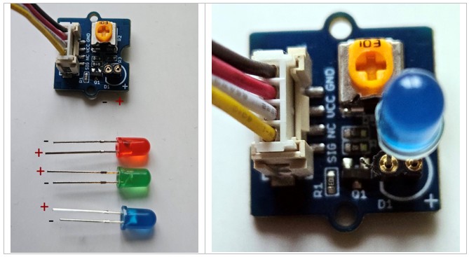
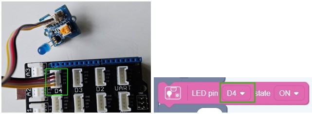
The LED module allows you to use three LEDs of different colors (red, green, and blue). Be sure that the anode (positive leg +) is connected to the right connector on the LED module:
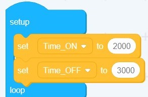
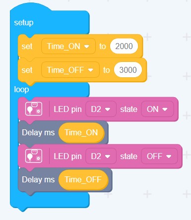
We will turn an LED ON and OFF changing the time the LED stays ON and the time it stays OFF. We will create two variables on the Setup procedure and assign them two different values (for example 2 seconds for the time ON and 3 seconds for the time OFF – the time must be entered in milliseconds!)
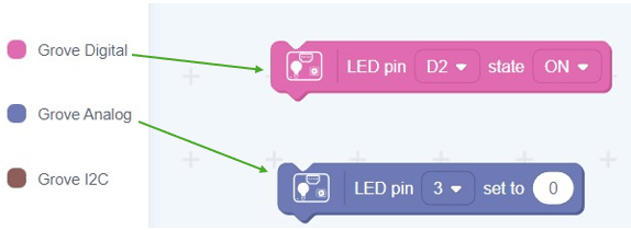
Be sure to select the correct port inside the program, where the LED is attached. For example if you connected your LED to D4, use D4 in you program:
Here is the code for this first example. The LED is connected to D2, and it will stay on for 2 seconds and 3 seconds off in a loop:
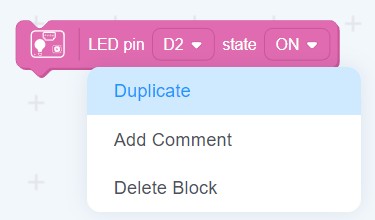
TIP: you can clone the blocks using the right mouse button and selecting „Duplicate“:
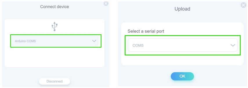
To upload your code to the Arduino, first select Connect and then Upload.
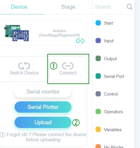
Check that the correct COM port is connected i.e., where your Arduino is:
LED breathing – LED as an analog output
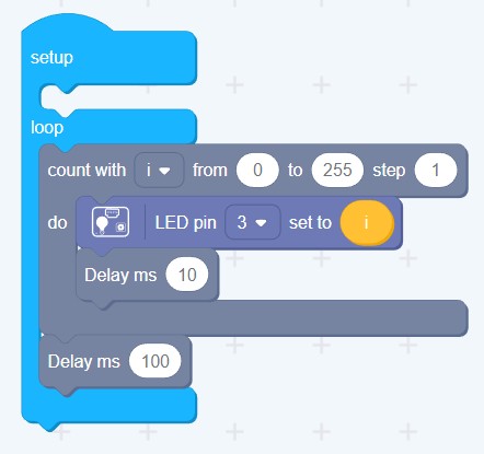
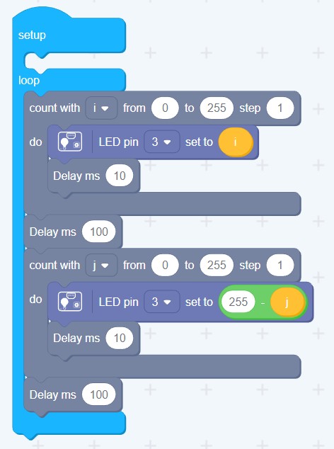
We can change the brightness of the LED, when we use it as an analog output. We will create a cycle inside the Loop to increase the brightness from 0 (dark) to 255 (maximum brightness) and then a cycle to go from 255 (maximum brightness) to 0 (darkness).
Here is the code for the first cycle, from darkness to brightness. The LED should be connected on D3:
And the code for both cycles, the LED looks like it is breathing:
Changing the blinking time using the rotary angle sensor
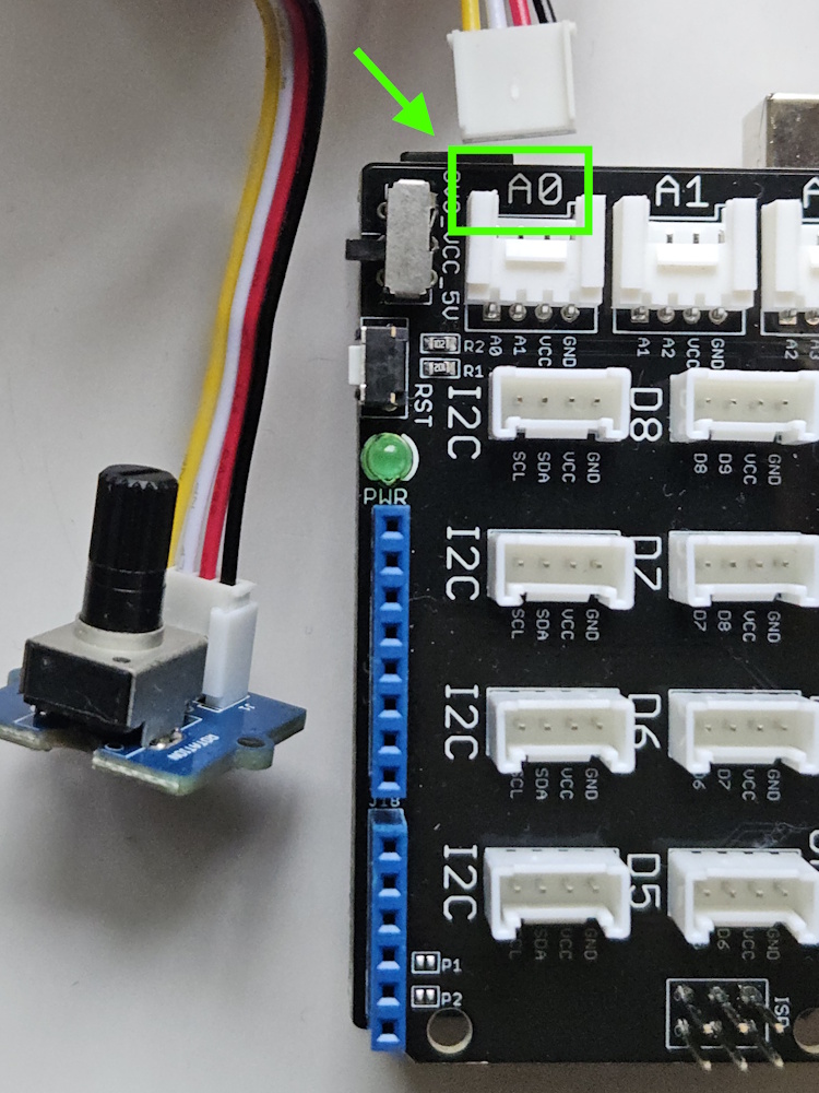
We can change the blinking time of the LED by reading the value of an input. We will use the Rotary Sensor as an analog input and we will connect it on A0:
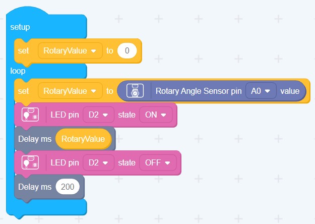
Code to change the time that the LED stays on by rotating the rotary sensor on A0:
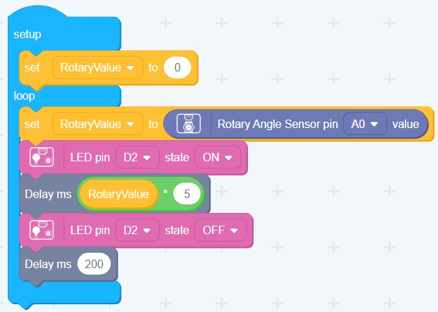
We can increase this time, multiplying the value of the rotary sensor by a constant, for example x5:
Controlling a servo motor with the rotary angle sensor
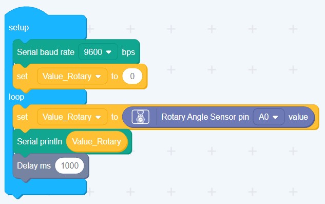
The rotary sensor gives an analog value between 0 and 1023. We can see the values using the Serial Monitor.
Before using the Serial Monitor we should set its baud rate first (the speed at which information travels through a communication channel. We set 9600bps for this example). To send a value to the Serial Monitor we use the instruction „Serial println“
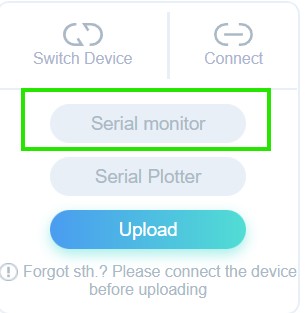
The window for the Serial Monitor can be opened from the left menu:
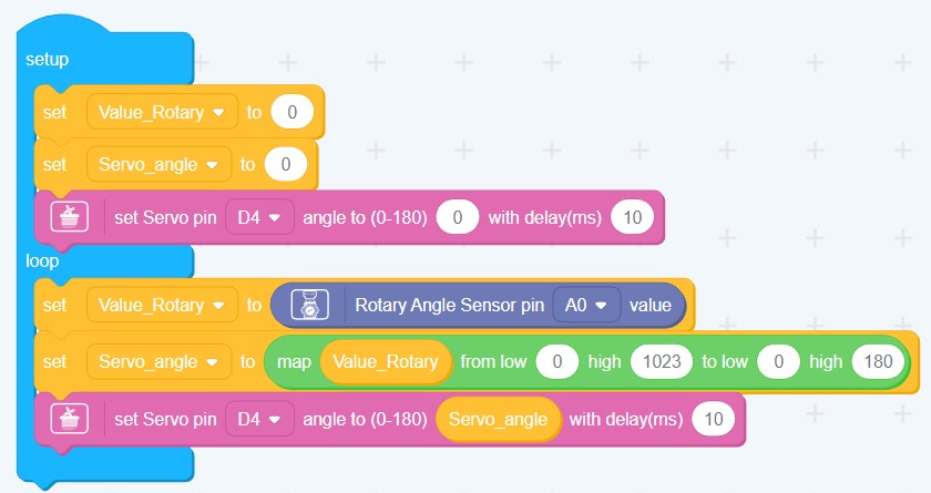
The servo motor can move between the angles 0° and 180°. We need to use the “map” function to transform the values from the rotary sensor into a valid value that the servo motor can read.
Using a light sensor to build a night-light.
The LED will light up when it gets dark. We can set the threshold, at which the LED should turn on.
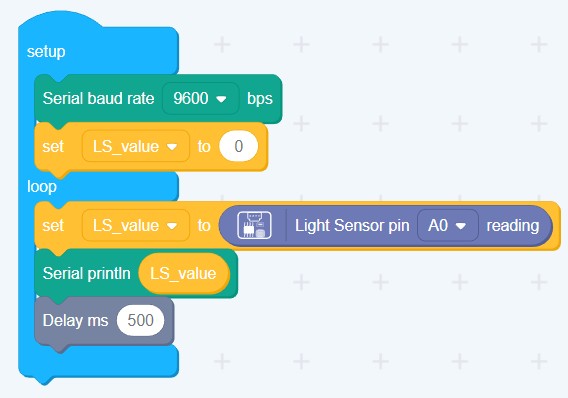
First, we read the values given by the light sensor on the Serial Monitor, to know which values mean that the room is dark:
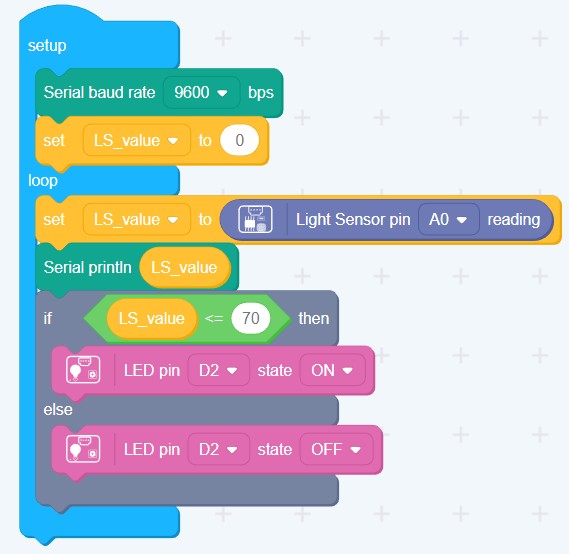
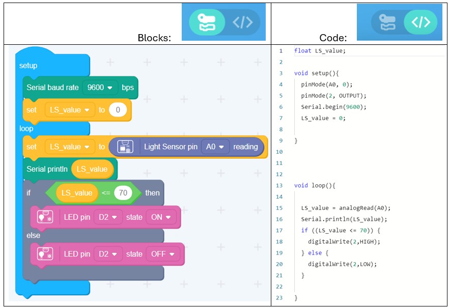
Once we’ve selected a threshold for the LED to be turned on, we can use an „If“ instruction to turn the LED on, i.e., only if the light sensor is below that value, the LED will be on, otherwise the LED will be off:
Code vs Blocks “translation”:
On the upper right corner there is a button that allows you to see the code translation of the blocks that you’ve used for your program:
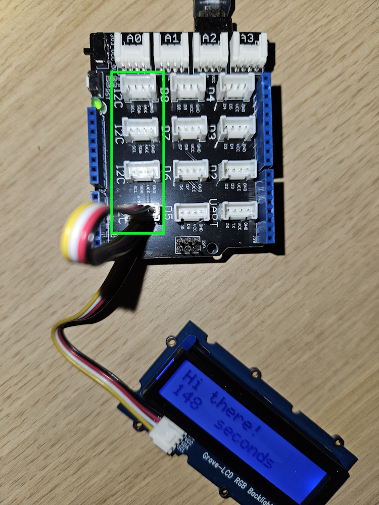
LCD-backlight show. Showing the system running time in seconds
Use any of the I2C ports to connect the LCD (Liquid Crystal Display):
The blocks for the LCD are inside the menu Grove I2C:
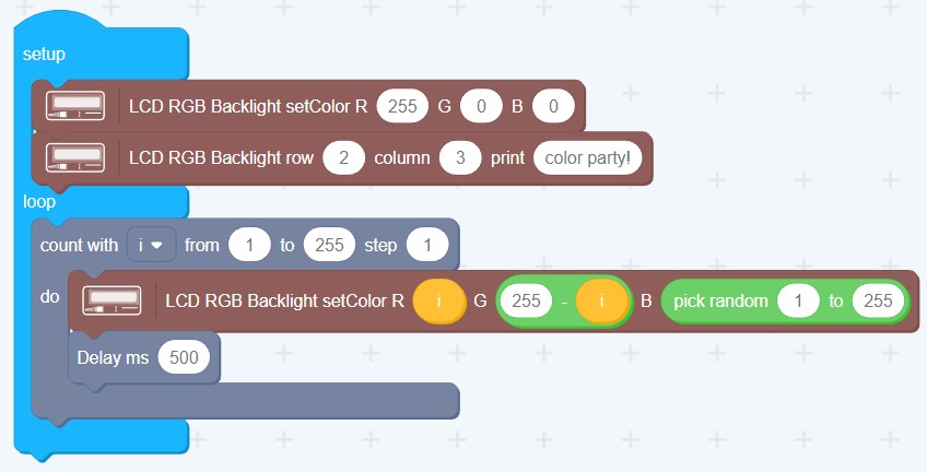
Code to change the color of the LCD’s background light in a loop:
Code to see a message and to show the running time since the Arduino was initialized. By default, this time comes in milliseconds, we divide by 1000 to show the time in seconds:

Doorbell – Touch sensor to turn on buzzer.
A short melody will be played by the buzzer when someone touches the touch sensor:
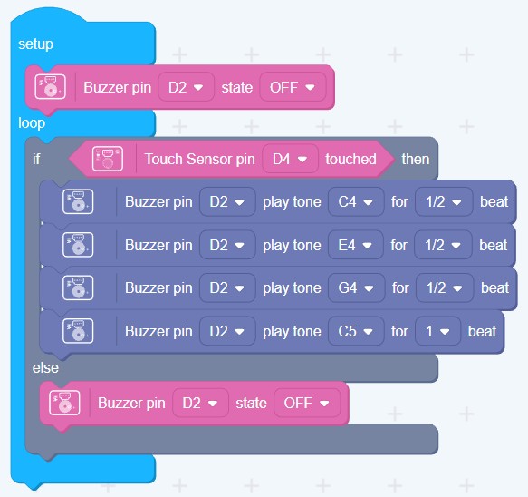
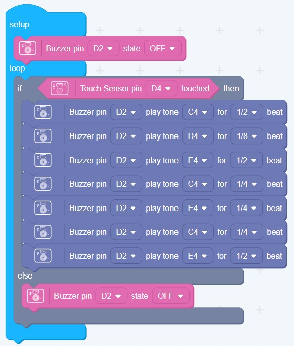
create different melodies:
Snapping to turn on a light – using the sound sensor
We can also use the Arduino IDE to program the Arduino, instead of Codecraft. Here is an example of a code to make an LED light up when you snap or clap near the sound sensor:
The program can be copied from the Grove’s site on Github: Grove-Github
Or here:
// Demo for Grove - Starter Kit V2.0// Turns on the Grove - LED when the sound level measured by the Grove - Sound Sensor exceeds a certain value.// Connect the Grove - Sound Sensor to the socket marked A0// Connect the Grove - LED to D7// Define the pins to which the sound sensor and LED are connected.const int pinSound = A0;const int pinLed = 7;// Define the sound level above which to turn on the LED.// Change this to a larger value to require a louder noise level.int thresholdValue = 500;void setup(){ // Configure LED's pin for output signals. pinMode(pinLed, OUTPUT);}void loop(){ // Read the value of the sound sensor. int sensorValue = analogRead(pinSound); // If the measured sound level is above the threshold, blink the LED. If (sensorValue > thresholdValue) { // Turn the LED on for 200ms, then turn it back off. digitalWrite(pinLed,HIGH); delay(200); digitalWrite(pinLed,LOW); }}
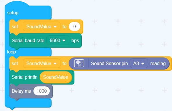
If you need to change the threshold value, it is better to use the Serial Monitor to see the values that the sound sensor is delivering.
// Connect the Grove - Sound Sensor to the socket marked A0// Define the pin to which the sound sensor is connected.const int pinSound = A0;void setup(){ // Configure the serial communication line at 9600 baud (bits per second.) Serial.begin(9600);}void loop(){ // Get the value of the sound sensor. int val = analogRead(pinSound); // Print this value to the serial console. Serial.println(val); // Wait one second between measurements. delay(1000);}
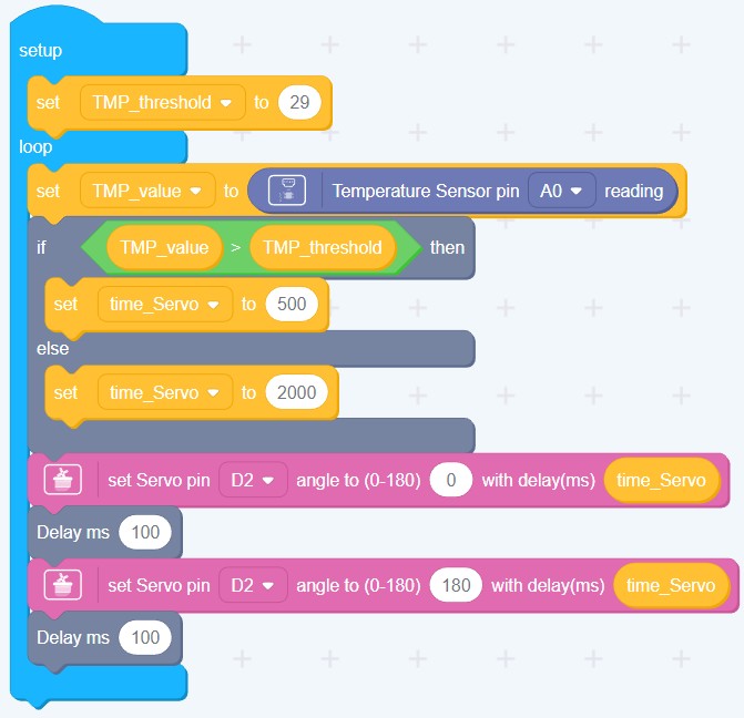
Using the Temperature Sensor to control a Servo Motor
The Grove – Temperature Sensor uses a thermistor, which returns the ambient temperature. The Arduino then converts this voltage value measured by an analog input pin to a temperature.
We can control the servo’s speed based on temperature: it moves faster once a specific threshold is met. This example shows a temperature-dependent control of the servo’s shaft speed:
(change the threshold value as needed)

Hinterlasse einen Kommentar